Archive
Individual Assignment: Advanced Microcontrollers & Wired/Wireless Communications [Wi-Fi signal + LED indicator]
In this assignment I have decided to work with the following set of post-it notes:

I wanted to make a LED indicator that shows how strong the Wi-Fi signal is by using the CUI32 board and BlinkM LED. The idea is that the BlinkM LED indicates if the Wi-Fi signal is strong or weak by turning into a specific color. Furthermore if there is no Wi-Fi signal at all the BlinkM LED will turn off. The following items describe how the concept works:
- If Wi-Fi signal is strong the BlinkM LED turns green.
- If Wi-Fi signal is between strong and weak the BlinkM LED turns blue.
- If Wi-Fi signal is weak the BlinkM LED turns red.
- If there is no Wi-Fi signal the BlinkM LED turns off.
Here is the BASIC code:
10 dim i, cmd as byte, r as byte, g as byte, b as byte, z as byte

20 rem -- stop script --

30 let cmd = 'o'

40 while 1 do

50   for i = 0 to 3

60     let cmd = 'c', r = 0x5*(i==2), g = 0x5*(i==0)

70     let cmd = 'c', b = 0x5*(i==1), z = 0x0*(i==3)

80     i2c start 0x9

90     i2c write cmd, r, g, b, z

100     i2c stop

110     sleep 5000 ms

120   next

130 endwhile

end
And lastly here is the concept video:
MEA10731 // Mini Project // conductor stand
For our mini project we chose to design and prototype a semester project related artefact. Our semester project is called Orkestrariet and based on a project call from DR for a new music experience center called Musikarium.
The Orkestrariet is an interactive music learning installation using finger tracking. Until now, the system needed to be activated/deactivated by pressing the enter key. For a public installation, this is definitely not an ideal input method.
So what device could improve the interaction? Verplank’s interaction design framework was used to design the concept this mini project is based on:

It was thus decided to build a wooden conductor stand for the user. So to trigger the application, the user needs to step onto the stand. The application status is indicated by a curtain in the interface. If the application is active, the curtain is open and displays the orchestra. If the application is deactivated, the curtain is closed. Stepping off the stand automatically ends the session thus closing the curtain, saving the user data and deactivating the system.


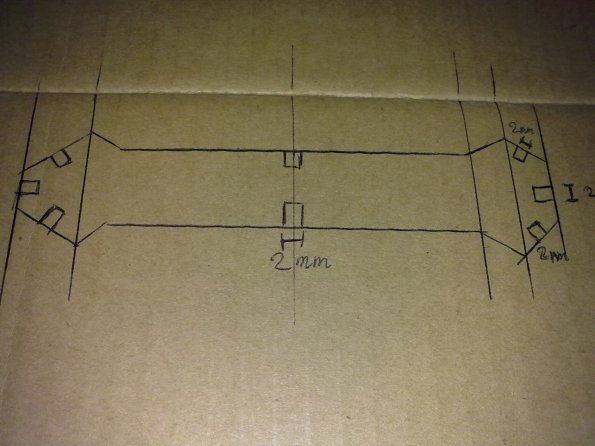
To register a user, a force sensitive resistor (FSR) was built into the stand. The following sketch illustrates the stand.
 The actual stand consists of the frame (image 1), a bottom plate mounted onto the frame with the FSR attached to it (image 2) and a plate losely placed on top of the bottom plate (image 3).
 image 1
 image 2
 image 3
For installation purposes, 2 footprints on the top plate indicate where the user needs to stand. Furthermore, an instruction plate was designed. It explains how to use the system.

The FSR is connected to a CUI32 board. Using a small program written for StickOS, the CUI32 sends the analogue input signal of the pin the FSR is connected to (an3) to a patch in MaxMSP.
StickOS program:
10 dim a as pin an0 for analog input
20 dim b as pin an1 for analog input
30 dim c as pin an2 for analog input
40 dim d as pin an3 for analog input
50 dim e as pin an4 for analog input
60 rem — pin an5 usurped by USB —
70 dim g as pin an6 for analog input
80 dim h as pin an7 for analog input
90 dim i as pin an8 for analog input
100 dim j as pin an9 for analog input
110 dim k as pin an10 for analog input
120 dim l as pin an11 for analog input
130 dim m as pin an12 for analog input
140 dim n as pin an13 for analog input
150 dim o as pin an14 for analog input
160 dim p as pin an15 for analog input
170 configure timer 0 for 10 ms
180 on timer 0 do print “A”,a,b,c,d,e,”0″,g,h,i,j,k,l,m,n,o,p
190 while 1 do
200 endwhile
Excerpt of the patch in MaxMSP:

The analogue signal is fed to a threshold which then controls the binary message from MaxMSP to Processing (sending 1 when the FSR detects pressure (any value >0) and 0 when there is no pressure). We used MaxLink External library in order to communicate from MaxMSP to Processing which is where the main Orkestrariet application is run. The received value (1 or 0) controls the activation/deactivation of the system.
The following video shows the working prototype of the conductor stand.
Laser cutter assignment (Martin Bach Nielsen)
For my laser-cutter assignment, I wanted to make a type of cut outs in the theme of mechanics (gears, cogs, tools etc), but still try to keep the individual pieces as universal as possible. This way, the cutouts could be used to create many different things, and not be specific pieces for a specific puzzle.
I started out with a few concept drawings seen here:
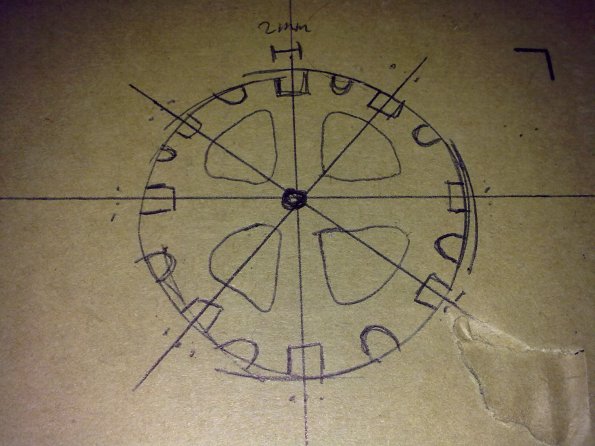
The “gear” like pieces have “hooks” in them in 8 different places on a full circle. The “wrench” pieces also have 8, but placed quite differently, 2 in the middle and 3 in each end. In the concept phase, the gears also had little rounded “U’s” in them. This was meant to be a place to put something like pneumatic pipes/hoses, but these were later discarded due to time constraints and laser cutter frustration 🙂
I then proceeded to draw them in 3DS max, and then got to redraw them in Autodesk due to software differences and the way they individually interpret splines.
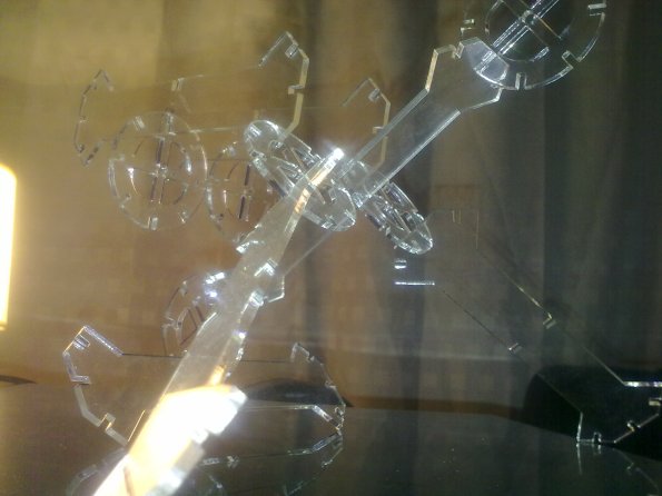
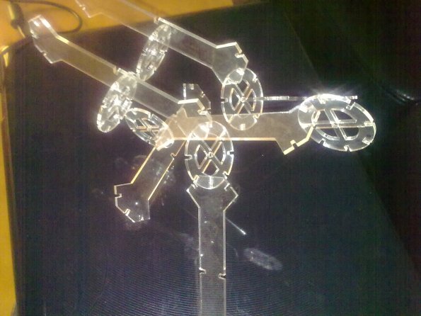
Here is a picture of the final two pieces. They didnt really turn out the way I had hoped, but alot of time went into actually producing them:)

And a picture of the final result. A fierce mechanic monstrosity made from these pieces.
Flash Cards exercise – Martin Bach Nielsen
The two words i drew from the flashcards were “Activity” and “LED”.
So I decided to make the BlinkM respond to activity via visual feedback. The only way to measure activity
available at the time was through mouse input.The movement speed of the mouse in both X and Y is then interpreted as activity by my Processing sketch,
and the BlinkM emits light based on the activity in this fashion:
- R(activity/25)
- G(activity/25)
- B(activity/25)
This results in a slow flashing when the mouse is moved around slowly, and gradually faster as the mouse
speed increases. A demonstration video is shown below. To really see it, I had to dim the ambient light,
which gives fairly poor image quality.
CODE
import thingm.linkm.*;
LinkM linkm;
void setup(){ size(1440, 990, P2D);
linkm = new LinkM();
try{ linkm.open();
}
catch(IOException ioe) { println(“exception” +ioe); }}
void draw(){
variableBlink(mouseX, mouseY, pmouseX, pmouseY);
}
void variableBlink(int x, int y, int px, int py) {
int speed = abs(x-px) + abs(y-py);
try{ linkm.fadeToRGB(9, speed/25,speed/25,0);
//linkm.off(9);
}
catch(IOException ioe) { println(“exception” +ioe);
}
}
void stop(){
try{ linkm.off(9);
}
catch(IOException ioe) { println(“exception” +ioe);
}
linkm.close();
}
END CODE
BlinkM Individual Assignment [Keyboard Trainer] – Daniel Collado
For my individual assignment using the BlinkM, I also used the Keyboard as input device.The application is a typing trainer, which calculates the time the user needs to type some colors given by the BlinkM LED.
The mechanic is the following:
- Run the application
- Immediatly, a random color will be displayed on the BlinkM LED
- The user must type the right letters as fast as possible
- If the letters have been typed correctly, the time spent on the task is displayed.
Right now the possible colors are red green and blue, but adding new colors wouldn’t be a problem. If any of the letters introduced on the keyboard are wrong, a message is displayed warinng the user about it, and the application ends.
Here you have a video of the testing:
mea10730 Rene Olesen and Casper Slynge Mini Project
Our mini project is based on an observed problem that various media campaigns have tried to reduce for years. The so called “right turn”-accidents, a scenario where a heavy vehicle (such as a truck) needs to make a right turn in an intersection, and hits a cyclist or a pedestrian who is heading straight forward. This is due to blind angles, and although these heavy vehicles are equipped with several mirrors, these accidents still occur.
Notifying the truck driver about these vulnerable road users is crucial, but at the same time, the notification should not be too disrupting, as the driver needs to keep his focus on maneuvering the vehicle. So if a system could be installed, that automatically warns the driver with a discrete alert, it could raise the awareness of the driver without interrupting his driving.
We have used Bill Verplank’s framework for interaction design to sketch out the concept:

By detecting the surrounding cyclists with proximity sensors, the system should send out vibrations to a corresponding area of the truck driver’s seat. For the implementation of the prototype, we used the CUI32 board to connect four proximity sensors to four cell phone vibrators, by mapping their i/o ports in the CUI software.


Our code looks as follows:
10 dim prox1 as pin an0 for analog input

11 dim prox2 as pin an1 for analog input

12 dim prox3 as pin an2 for analog input

13 dim prox4 as pin an3 for analog input

20 dim vibe1 as pin rd1 for digital output open_drain

21 dim vibe2 as pin rd2 for digital output open_drain

22 dim vibe3 as pin rd3 for digital output open_drain

23 dim vibe4 as pin rd4 for digital output open_drain

30 dim threshold

40 let vibe1 = 0, vibe2 = 0, vibe3 = 0, vibe4 = 0, threshold = 1100

50 while 1 do

60   print prox1, prox2, prox3, prox4, vibe1, vibe2, vibe3, vibe4

100 	if prox1 > threshold then

110    	let vibe1 = 1

120 	endif

130   if prox1 < threshold then

140    	let vibe1 = 0

150   endif

200  	if prox2 > threshold then

210    	let vibe2 = 1

220   endif

230   if prox2 < threshold then

240    	let vibe2 = 0

250   endif

300   if prox3 > threshold then

310    	let vibe3 = 1

320   endif

330   if prox3 < threshold then

340    	let vibe3 = 0

350   endif

400   if prox4 > threshold then

410    	let vibe4 = 1

420   endif

430   if prox4 < threshold then

440    	let vibe4 = 0

450   endif

460   sleep 100 ms

470 endwhile
To heighten the authencity of the prototype, we acquired a toy truck and mounted the proximity sensors on it. The following video demostrates the prototype in action. It can be difficult to see the vibrators moving, but it does work as intended.
Note: For the poster created for this concept, please check out our previous blog post.
– Casper & Rene
Advanced Microcontrollers & Wired/Wireless Communications assignment by Martin Weiss Hansen
For this assignment I chose the post-it pair: Microphone + noisy environment:

I wanted to do a decibel meter for use with a laptop. A decibel meter measures the sound level of the environment. Measuring the sound level is important because high sound pressure levels are harmful for human ears. The microphone of the laptop registers the sound level, and an LED lights red if the sound is harmful, green otherwise.
Processing and Max/MSP have been used for the prototype. MaxLink is used to send data from Max/MSP to Processing and from Processing to a BlinkM which is connected through a LinkM USB programmer. Examples from MaxLink are used as a basis for the prototype.
The following is a demonstration video (please note: for the video there was no LinkM/BlinkM available, a screen set up by Processing was used instead):
Further iterations of the prototype could include other sensors to detect the state of the environment.
Individual Assignment: Thermometer Exercise [Room Temperature]
For this assignment I have chosen to work with room temperature by using the CUI32 board, RGB LED-strips, TMP102 sensor and a small piezo speaker. The idea behind this concept is that the RGB LED-strips indicate if it is comfortable, too hot or too cold in a room by blinking a certain color depending on the temperature, which is measured by the TMP102 sensor. Additionally the piezo speaker plays a warning tone if it is too hot or too cold in a room, but if it is comfortable it mutes. The following items describe how the system works:
- If room temperature is between 20° – 30 ° the RGB LED-strips turn green (comfortable) and no warning tone is played.
- If room temperature is > 30° the RGB LED-strips turn red (too hot) and a warning tone is played.
- If room temperature is < 20° the RGB LED-strips turn blue (too cold) and a warning tone is played.
Here is the BASIC code:
10 dim i, j

12 dim audio as pin rd1 for frequency output

20 dim cmd as byte, rsp[2] as byte

30 dim temp

40 dim leds[20] as byte

50 dim latch as pin rg9 for digital output open_drain

60 dim sync as pin rg6 for digital output open_drain

70 let latch = 0, sync = 0

80 while 1 do

81   if temp>30 then

82     let audio = temp*80

83   elseif temp<20 then

84     let audio = temp*40

85   else

86     let audio = 0

87   endif

101   print temp

121   let j = j+1

122   for i = 0 to leds#-1

123     if temp>30 then

124       let leds[i] = 0x80+0x4*(i==j%leds#)

125     elseif temp<=30&&temp>=20 then

126       let j = j+1

127       let leds[i] = 0x80+0x3

131     elseif temp<20 then

132       let j = j+1

134       let leds[i] = 0x80+0x10*(i==j%leds#)

135     endif

136   next

137   qspi leds

140   let latch = 1, latch = 0

150   let cmd = 0

160   i2c start 0x48

170   i2c write cmd

180   i2c read rsp

190   i2c stop

200   let temp = rsp[0]

240 endwhile

end
And finally here is the concept video:
MEA10732 miniproject (RhythmBox)
Introduction
In this miniproject we have chosen to present concepts from the course which have been used in our semester project which is entitled “RhythmBox”. This has resulted in a miniproject closely related to our semester project. Because of this, the title of the miniproject is the same as our semester project.
In this documentation, the miniproject will be described according to the following topics:
- Concept design
- Interface prototyping
- System design
- Conclusion
1. Concept design
Our semester project is based on a project proposal from Danmarks Radio called Musikariet. Initially the goal was to create a concept for teaching children about music. From the beginning we wanted to combine sound and graphics in the creation of such a concept.
The first concept that was developed was a mixture of the classic computer game “Pocket Tanks” and a music game. The purpose of this game was to create a team-player based application. In the initial scenario the number of players were two. One of the players controls the angle of the gun on the tank by completing a rhythm related task. The precision of the player when solving the task is translated to a precision in the angle of the gun. The other player controls the power of the gun by completing a melody related task. See a concept sketch by clicking the link below.
A few iterations on this concept was created. After this, another concept was developed. The idea was that two users collaborate using a piano on the wall to play a melody. The concept was named PianoWall. See the demonstration video below.
The PianoWall concept was discarded because it turned out to be more difficult than first assumed. Another concept was developed, a collaborational rhythm game where the users claps their hans and taps their feet. See the video below.
Different patterns for the tapping pads are shown in the pictures below.

Rhythm game pad pattern 1

Rhythm game pad pattern 2

Rhythm game pad pattern 3
The collaborational rhythm game concept was discarded because we didn’t come up with a reasonable solution for adding visuals to the system. However, an iteration of this concept ended up developing into the concept used in the semester project. This concept was called RhythmBox and is a one-player rhythm game which used graphical and audible feedback. The user sees and listens to a rhythm, afterwards the rhythm is replicated only with visual support. Sketches of the graphical user interface of different iterations of the concept are shown below.

Graphical user interface sketch 1

Graphical user interface sketch 2
On the background of these sketches it was chosen to simplify the concept. The system can be used by one player at the time instead of two and the visual representation of the rhythm events is simplified. See the screenshot from the actual application below.

Screenshot from the actual application
2. Interface prototyping
RhythmBox was created by using Bill Verplank’s design framework. See the pictures below.

Bill Verplank's design framework 1/2

Bill Verplank's design framework 2/2
- IDEA: Enhancing the process of rhythm teaching for the children aged 7-13.
- METAPHOR: Visualizing and projecting the rhythm on a big screen.
- ERROR: Usually the children don’t have any visual support in a teaching situation.
- SCENARIO: The setup could be used as an interactive exhibition at Musikarium.
- MODEL: Using a simple input; a glow with a piezo sensor and a CUI32 board. Getting a visual feedback in terms of graphical and audible representation of the rhythm.
- DISPLAY: Using a big screen with graphical and audible representation of the rhythm.
- TASK: First listen to the rhythm and then try to replicate the rhythm.
- CONTROL: Using the clapping gesture to master the task.
3. System design
Based on the concept described above, an application was implemented in Java. The application is structured in three different modules, following the model-view-controller architecture. See the figure by clicking the link below.
RhythmBox system design diagram
- Audio Module (Model): Manages the audio files and sampling.
- Graphic Module (View): Manages the graphical part of the application.
- Input Module (Controller): Manages sensor input using a CUI32.
The input module will be described here, as it uses concepts from the CDPT course. The module handles user input via a sensor glove. The clapping gesture was chosen to be the type of interaction for RhythmBox. Furthermore a film piezo sensor was used to detect the clapping input and sewn into the glove, in order to make it more intuitive for the user. See the image below.

Glove with a piezo sensor sewn into the palm
The BASIC code used to get the input from the glove using the CUI32 is listed below:
10 dim a as pin an1 for analog input
20 while 1 do
30   if a>600 then
40     print "1"
50     sleep 250 ms
60   endif
70 endwhile
The Java code to handle input via USB serial communication is listed below:
public class InputManager implements SerialPortEventListener{

public void serialEvent(SerialPortEvent event){
     switch (event.getEventType()) {
	case SerialPortEvent.OUTPUT_BUFFER_EMPTY:
           break;
	case SerialPortEvent.DATA_AVAILABLE:
           // we get here if data has been received
           byte[] readBuffer = new byte[20];
		try {
		// read data
		while (inputStream.available() > 0) {
			int numBytes = inputStream.read(readBuffer);
		}
		//Parse the data and trigger events here.
	} catch (IOException e) {}
		break;
	}
}
}
As we can see in the piece of code above, the javax.comm library provides a class called SerialPortListener, and uses a method call serialEvent, which listens on the serial port and checks its state. It runs a piece of code when new data is available.
4. Conclusion
Through the development of the concepts presented in this miniproject experience have been gained on how to develop concepts, and how to realize them. When developing a concept it is important to start off by evaluating a simple version of this concept, to avoid problems caused by involving too many variables.
Originally the concept included two players which should collaborate. When testing the prototypes internally in the group it became clear that the implementation of a collaborational concept would not be realistic in proportion to the other hypothesis stated in the semester project. The simplified concept was used to test two hypotheses in the semester project:
- H1: The error rate when replicating a rhythm is lowered significantly when the first of two runs is enforced to be a listening run as compared to doing two runs of replicating.
- H1: The error rate when replicating a rhythm is lowered significantly by using both audio and adding visual support.
Thermometer exercise – CUI32/LED Strip – Martin Bach Nielsen
For this exercise, I decided to try and incorporate a thermometer with auditive and visual feedback into clothing. The idea being that people suffering from low tolerance to body temperature changes (a condition that I apparently totally made up), would be able to have a type of security everywhere they go.
The most obvious place to put a colored LED strip would be in the sleeves of a shirt, since it fits the length, and this part of your body is always within visual range. I used the CUI32 to control the LED’s and a small piezo speaker. The algorithm on the CUI is fairly simple, which I will try to outline here:
- If body temperature is below the norm, the LED’s are green and no sound is played
- If body temperature rises higher than the norm, the LED’s turn red and a warning note is played.
- For every degree (this incrementation might need to be finer than 1 degree), the temperature rises, the note will also rise in pitch.
- Warning note and sound will disappear if the temperature drops below normal again.
Below is the BASIC code that the CUI is running and after that, a demonstration video of how the concept prototype turned out
CODE
